In software engineering, Unified Modeling Language (UML) offers a standardized method for visually representing, specifying, building, and documenting complex software systems. The goal of this in-depth manual is to clarify the significant importance of UML in software development. We will examine the different kinds of UML diagrams, their significance, and the process of making them. We will also talk about the best ways to use them.
What is UML?
The visual language known as Unified Modeling Language, or UML, has taken over as the accepted norm for software modeling and design. UML, which was first created by Grady Booch, Ivar Jacobson, and James Rumbaugh, offers a common language and set of guidelines for describing a system’s behavior and structure.
Types of UML Diagrams with Examples
There are different types of UML diagrams for different purposes in software development, such as Class, Sequence, Use case, Activity, Component etc. They make complex concepts easier to understand, improving software design clarity.
Class diagrams
Class diagrams, which show a system’s static structure, are the cornerstone of the UML. Classes are represented, together with their methods, properties, and relationships, in a class diagram. Let’s look at a more complex example, a class diagram of a banking system:
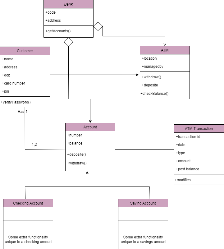
Here, classes such as `Account`, `Transaction`, and `Customer` are interconnected, depicting the relationships and attributes.
Use Case Diagrams
Use case diagrams highlight how a system interacts with its external actors. Going one step further, let’s examine a thorough use case diagram for a Hospital Reception system:
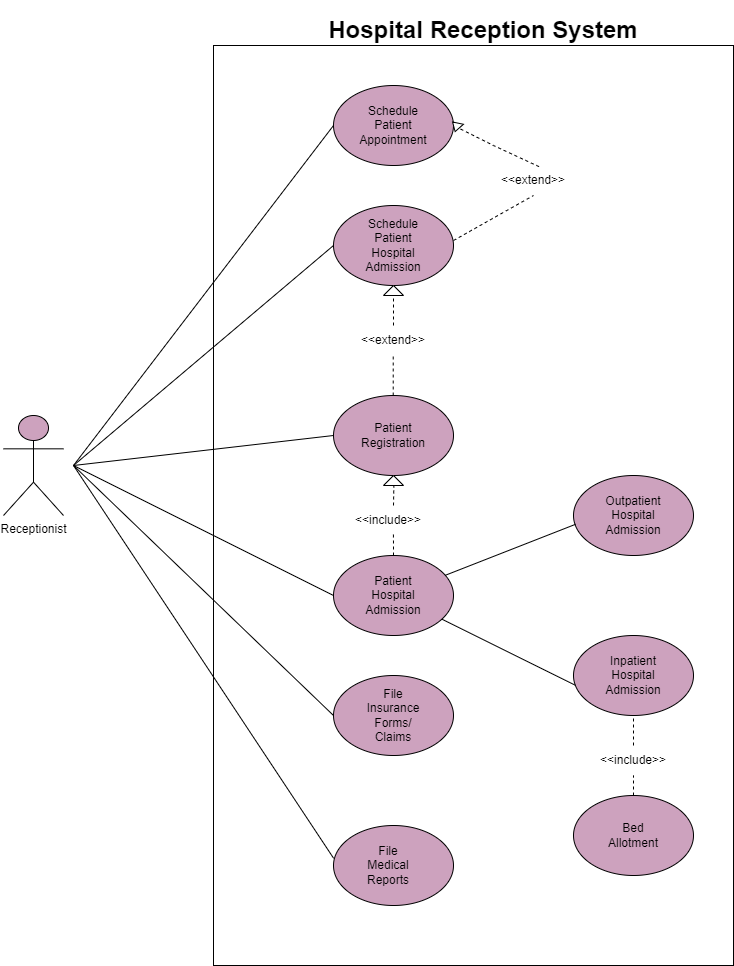
In this diagram, actors like `Receptionist’ interact with various use cases, elucidating the functionalities of the system.
Sequence Diagrams
Sequence diagrams illustrate the order in which items interact to provide insight into a system’s dynamic behavior. Let’s examine a sequence diagram of an online shopping process, for example:
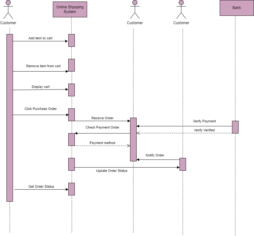 The interactions between `User`, `Shopping Cart`, and the `Payment Gateway` are meticulously outlined, capturing the chronological flow.
Activity Diagrams
The flow of activities inside a system is visually represented by activity diagrams. Take a look at a more detailed illustration of a vacancy submission of a recruitment system:
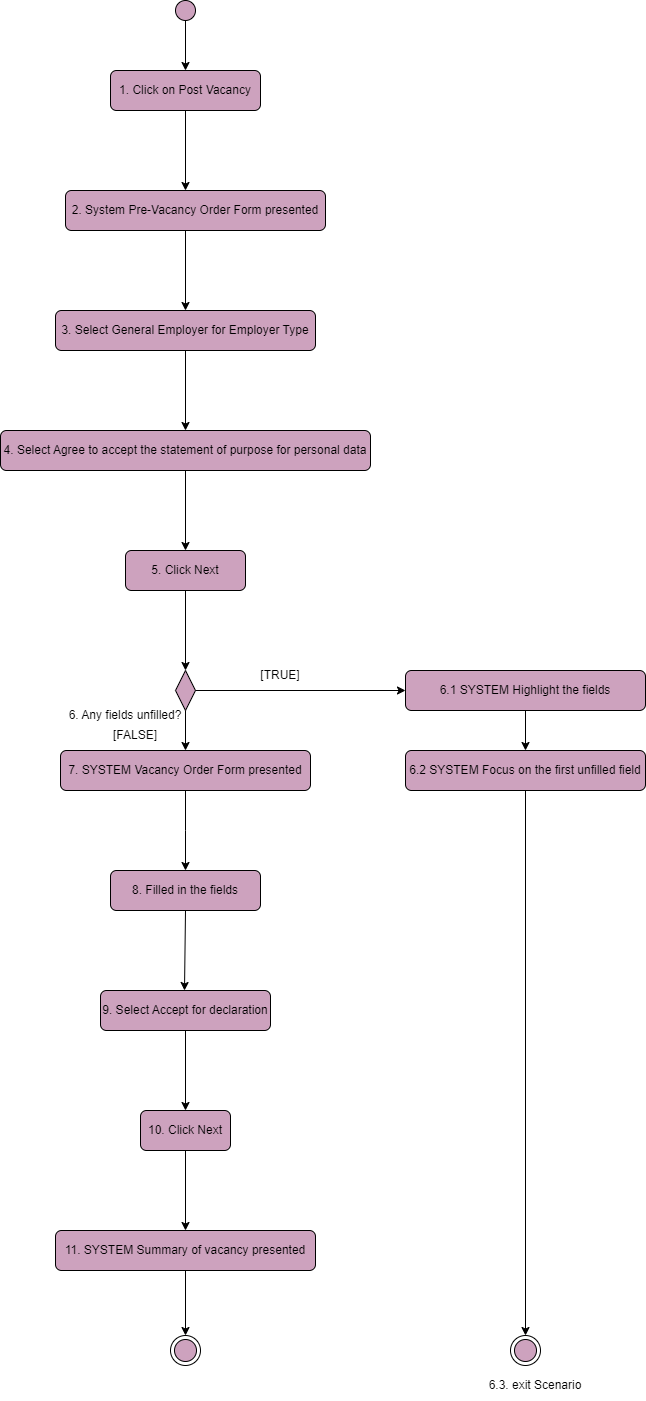 This diagram unravels the sequential steps involved in the vacancy submission of a recruitment system, providing a comprehensive overview.
State Machine Diagrams
State machine diagrams simulate an object’s various states as well as their transitions. Let’s examine an elevator system state machine diagram:
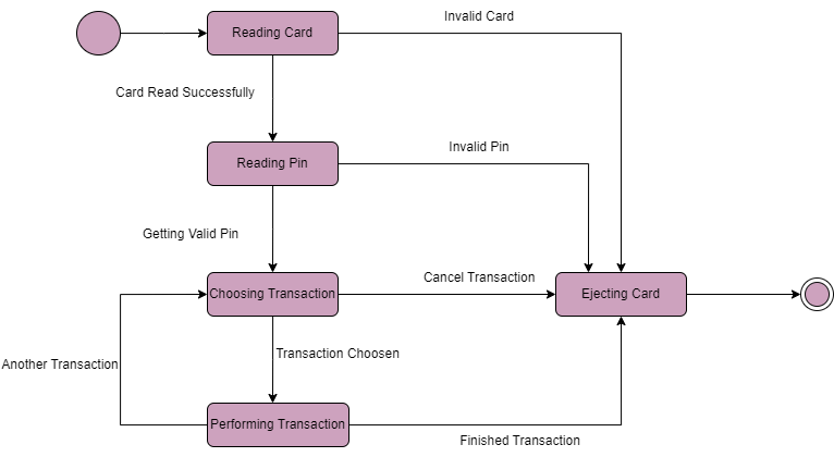
This diagram delineates the states of the ‘Rending card’– `Rending pin`, `choosing transaction`, ‘Performing transaction’, ‘Ejecting Card’– along with the transitions between them.
Component Diagrams
Component diagrams show the relationships between a system’s physical components. Building on the example we used earlier, take a look at an e-commerce platform’s component diagram:
![]()
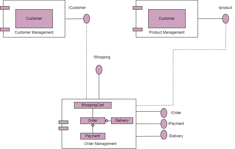
This diagram provides a holistic view of the physical components such as `Customer Management`, `Order Management`, and `Product Management`.
Why are UML Diagrams Important?
UML diagrams have several applications in software development:
- Communication Enhancement: UML serves as a common language for team members, stakeholders, and other departments engaged in the software development lifecycle, facilitating successful communication.
- Visualization Aid: UML diagrams provide developers with a visual representation of complex systems, which facilitates their understanding, analysis, and design refinement.
- Documentation Backbone: With UML, you can make sure that all design choices, system architectures, and interface details are well-documented for future reference.
- Design Validation: UML diagrams reduce the chance of errors and improve the overall quality of software by making it easier to validate and improve designs prior to real implementation.
How to Create UML Diagrams: Tools and Guidelines
You can learn to create UML diagrams effortlessly using different software applications described in the section below. You can also follow the guidelines given below, to generate more accurate diagrams for your projects. Explore these tools and tips in the upcoming sections.
Tools for UML Diagrams
With capabilities like version control, collaboration, and a variety of UML diagram types, several tools make the process of creating UML diagrams easier. Below are 3 popular tools used for UML diagrams.
- Lucidchart: A web-based tool with a plethora of UML templates and collaborative features.
- Draw.io: An open-source and free-to-use diagramming tool with UML support.
- Visual Paradigm: A comprehensive UML modeling tool offering a user-friendly interface.
Guidelines for Creating UML Diagrams
- Consistency: To guarantee clarity and readability, keep all diagrams consistent in their notation and naming conventions.
- Simplicity: UML diagrams should be clear and concise, free of extraneous details that could confuse team members.
- Reusability: To encourage the reuse of standardized components across several diagrams and ensure consistency, make use of stereotypes and templates.
- Regular Review: UML diagrams should be reviewed and updated on a regular basis to accurately reflect the current state of the system as the program develops.
Best Practices for UML
You can follow these recommendations to maximize the potential of UML:
- Foster Collaboration: To ensure a thorough and accurate representation of the system, encourage team members to collaborate during the UML modeling process.
- Iterative Modeling Approach: Adopt an iterative process for UML modeling so that it can be continuously improved and refined in response to user feedback and changing needs.
- Version Control Implementation: Use version control when working with UML diagrams to keep track of modifications and preserve an accurate record of design choices.
- Alignment with Code: Make sure UML diagrams and real code are in perfect alignment to foster consistency between design and implementation.
- Training and Documentation: To help with knowledge transfer and onboarding, train team members on UML and keep thorough documentation.
Conclusion
To conclude, UML diagrams are vital tools empowering developers to communicate, visualize, and document complex systems. Beyond diagrams, understanding UML types and best practices improves teamwork and project outcomes. For expert software consultancy on UML and related matters, contact software consultants at SLC. Harness the dynamic language of UML to enhance efficiency and future-proof your software design journey.